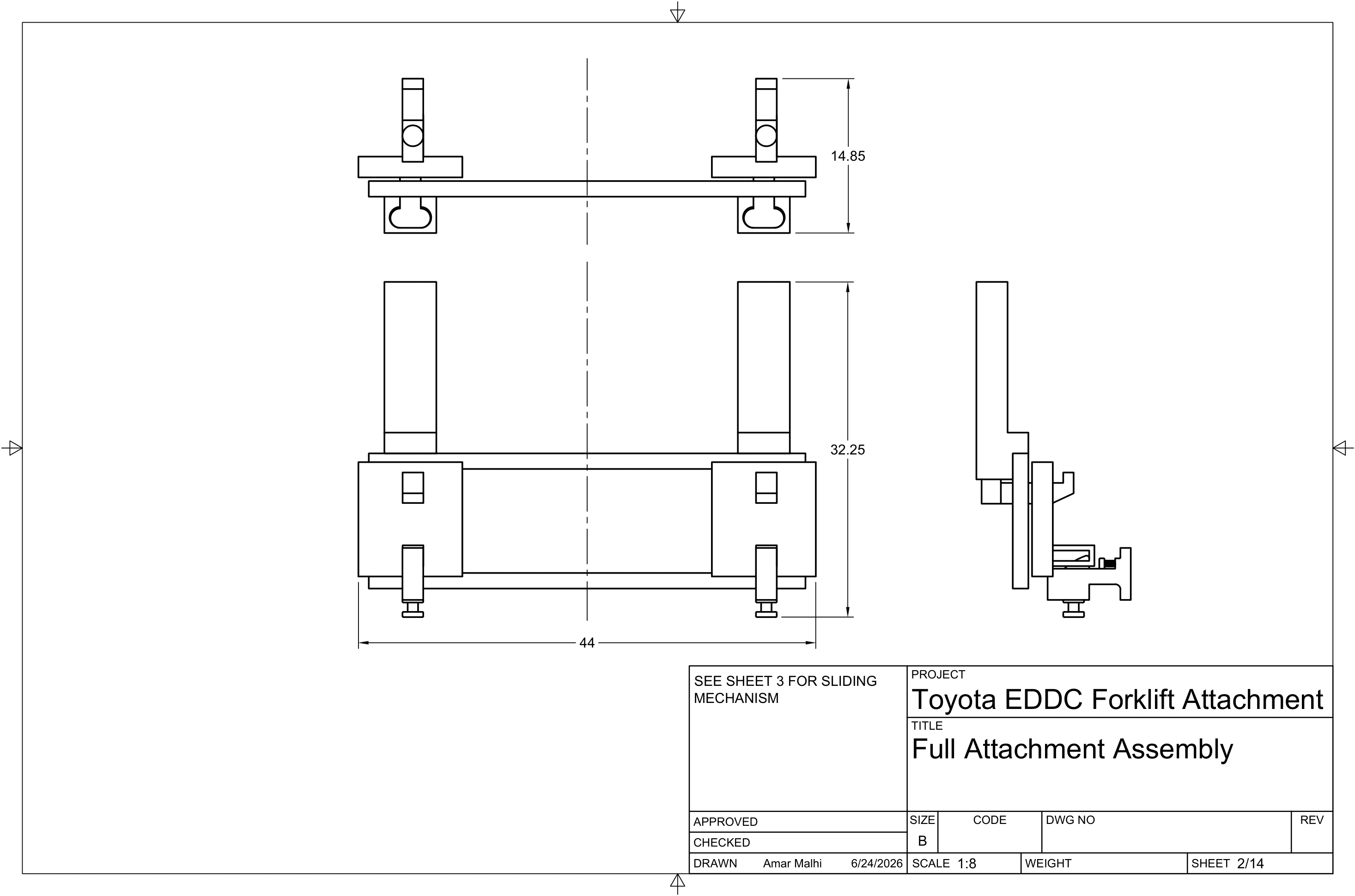
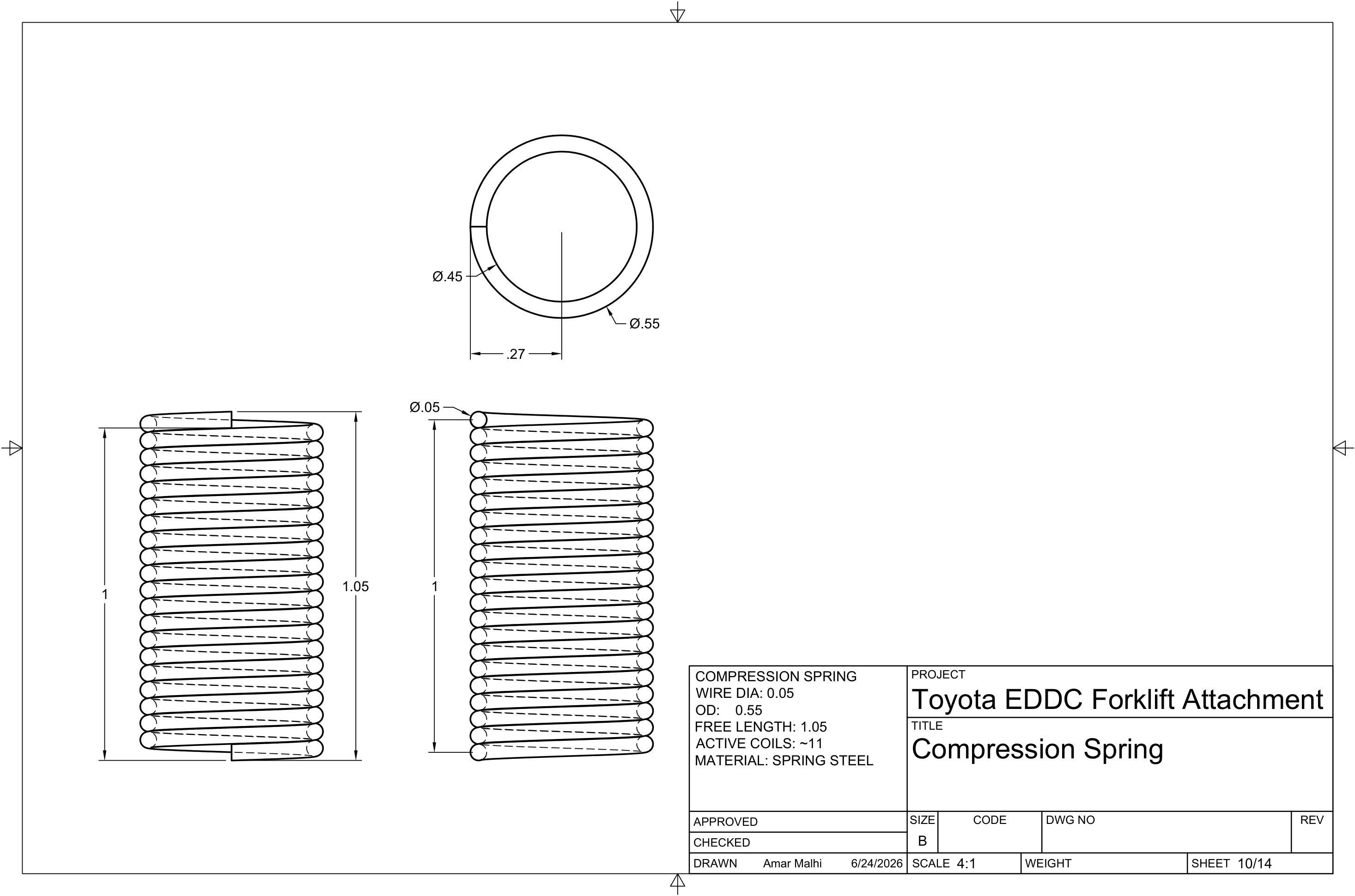
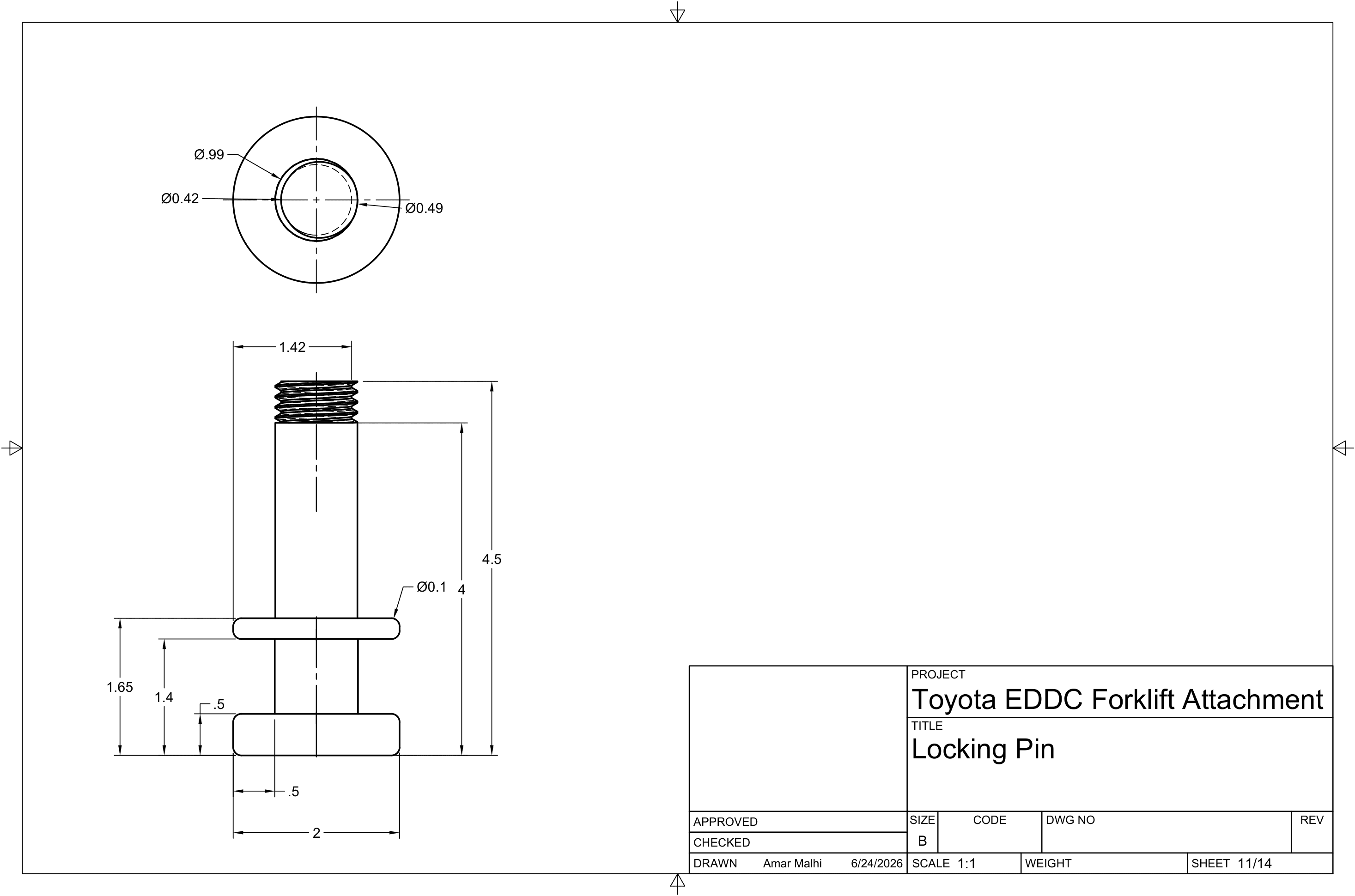
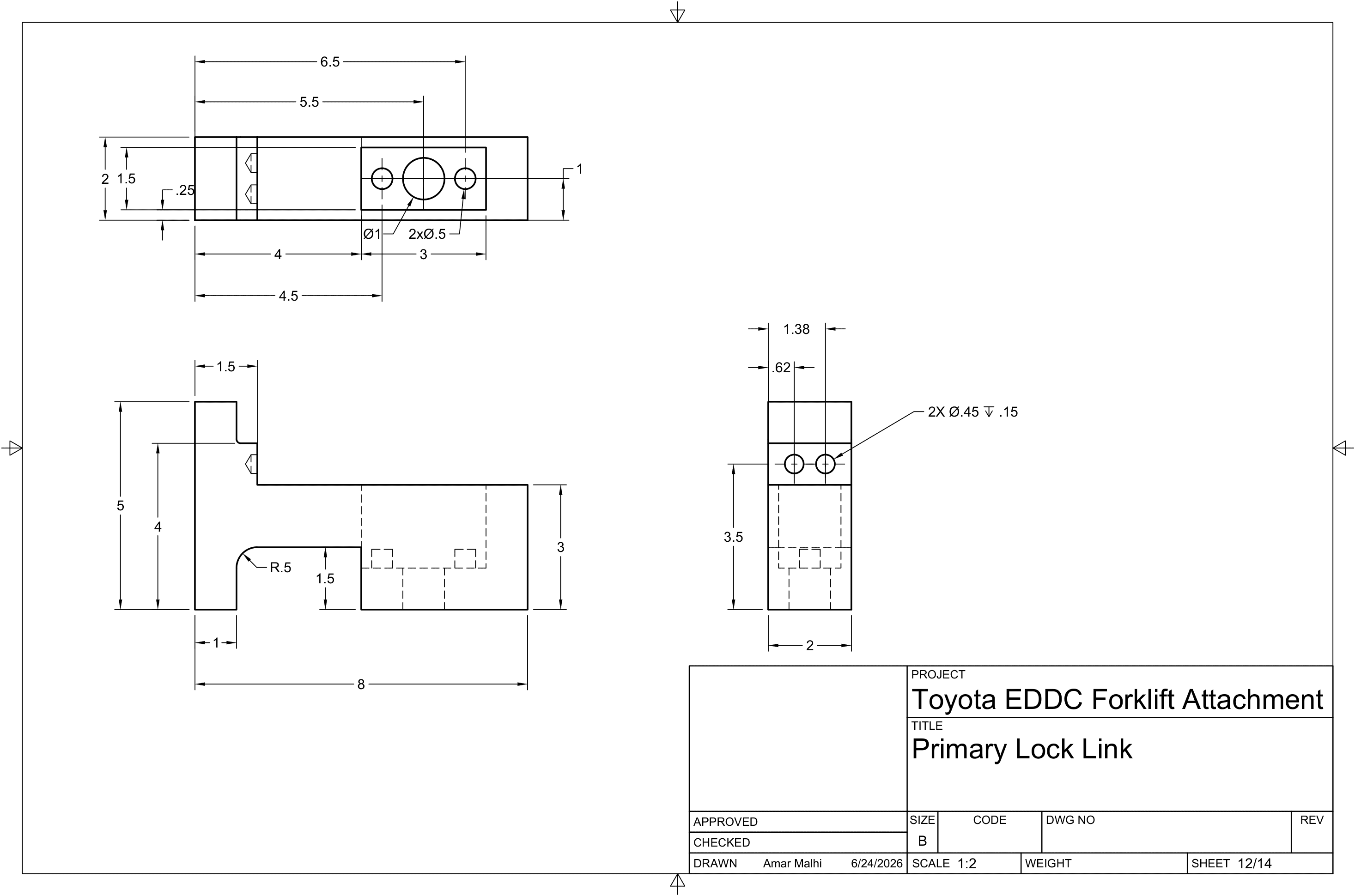
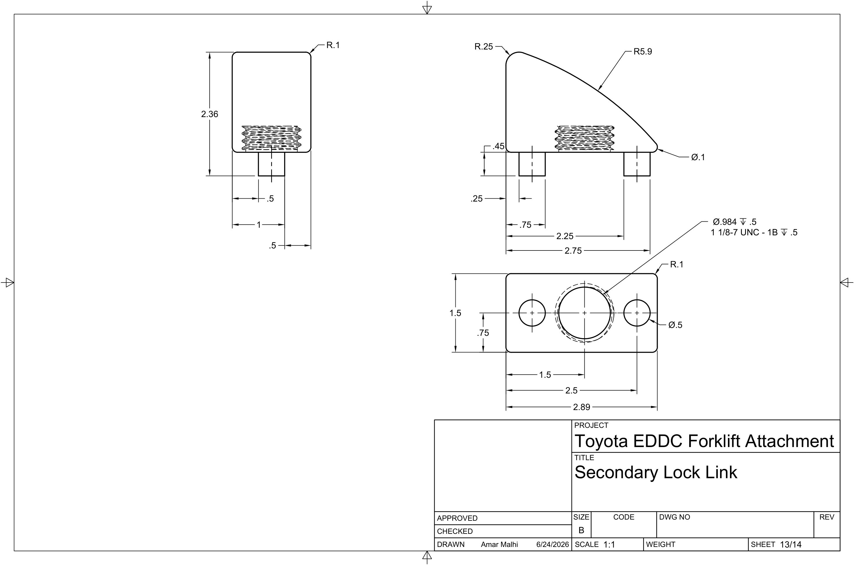
Full Attachment Assembly & BOM
FA-SHT-001
Projects
Fusion 360 modular forklift attachment for the CSUN × Autodesk × Toyota Materials Handling EDDC — five ITA / ISO 2328 carriage-height mounting classes, passive hook-lock, and linear-static FEA material trade study.
Jan 2025 — Apr 2025
| Requirement | Specification |
|---|---|
| Competition | CSUN × Autodesk × Toyota Materials Handling EDDC |
| Objective | Universal modular attachment for counterbalanced forklifts |
| Mounting range modeled | Five ITA / ISO 2328 carriage-height classes (I–V pin holes) |
| Power source | None — fully mechanical quick-release system |
| Structural reference | ANSI/ITSDF B56.1 load assumptions for FEA |
| Design tool | Autodesk Fusion 360 |
Carriage “Class I–V” here means ITA / ISO 2328 fork-carriage mounting heights (pin-hole spacing), not OSHA powered-industrial-truck type Classes I–V (electric rider, IC truck, etc.). ISO 2328 also defines related hook-on fork arm carriage interfaces (commonly discussed as Classes II–IV); this design’s adjustable bracket targets the five carriage-height pin positions used in the competition brief.
| Carriage Class | Approx. Carriage Height | Reference Capacity Band |
|---|---|---|
| Class I | 13 in | < 2,200 lb |
| Class V | 28.66 in | 17,602 – 24,198 lb |
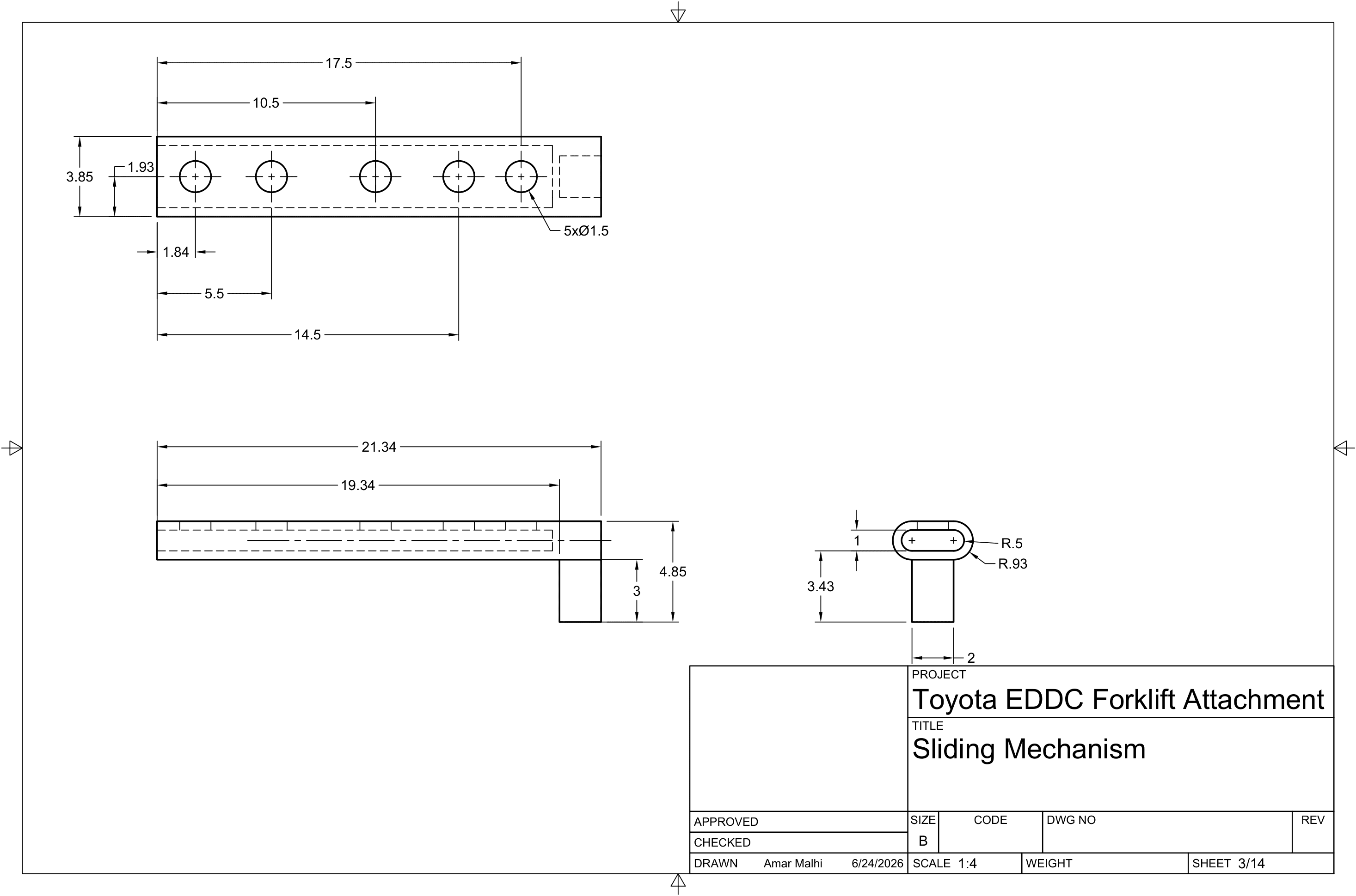
Component 2 uses five spaced pin holes matching each carriage height. One locking geometry works across classes once the bracket is pinned to the correct hole. Classes I and V are shown as the envelope; intermediate classes use the intermediate pin holes.
| Component | Function | Key Feature |
|---|---|---|
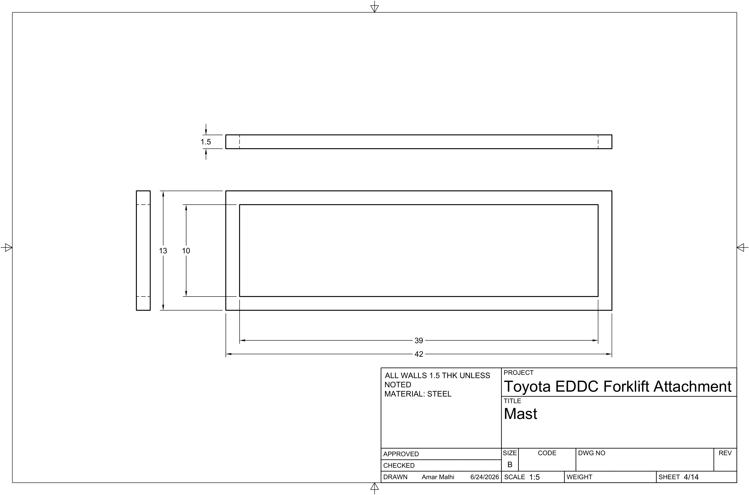
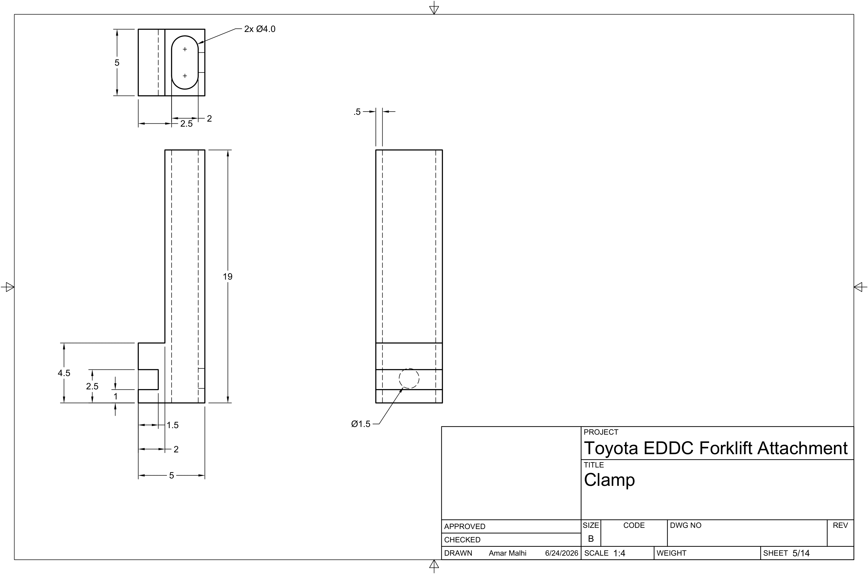
| Component 1 — Base Clamp | Mounts to forklift mast | Top clamp bracket; primary structural interface |
| Component 2 — Height Adaptor Shell | Carriage-height adjustment | 5 pin holes spanning Class I (13") to Class V (28.66") |
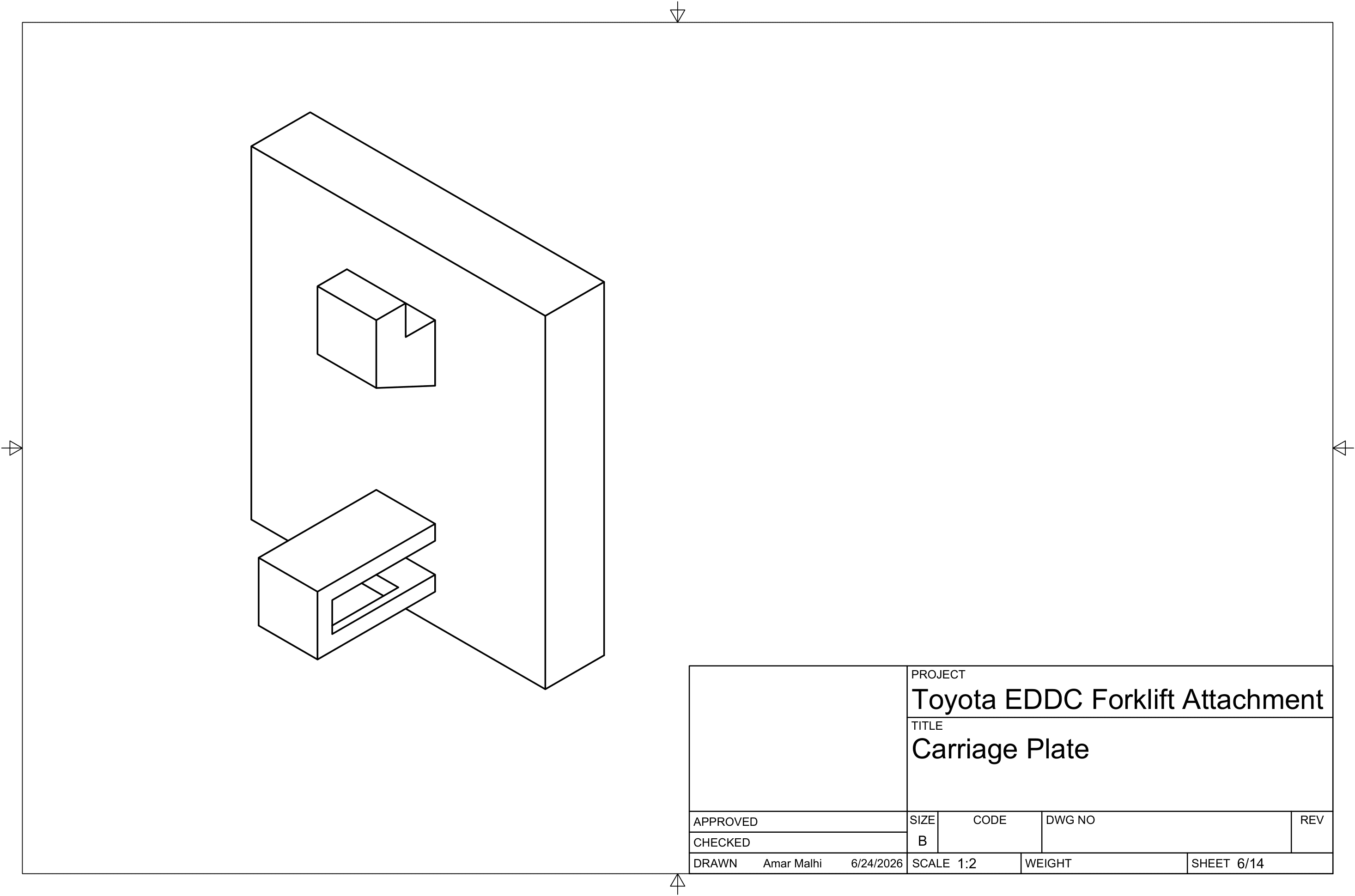
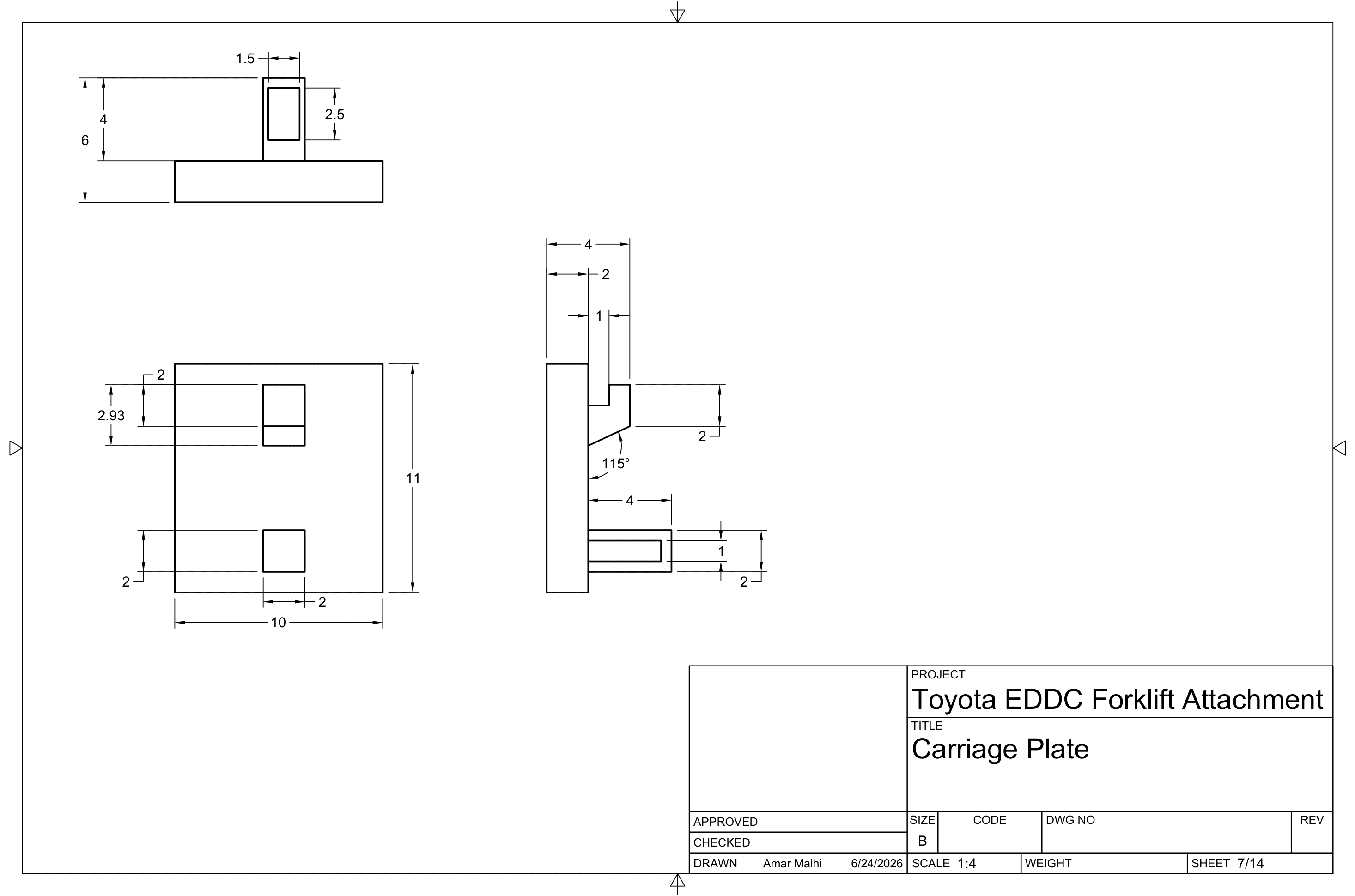
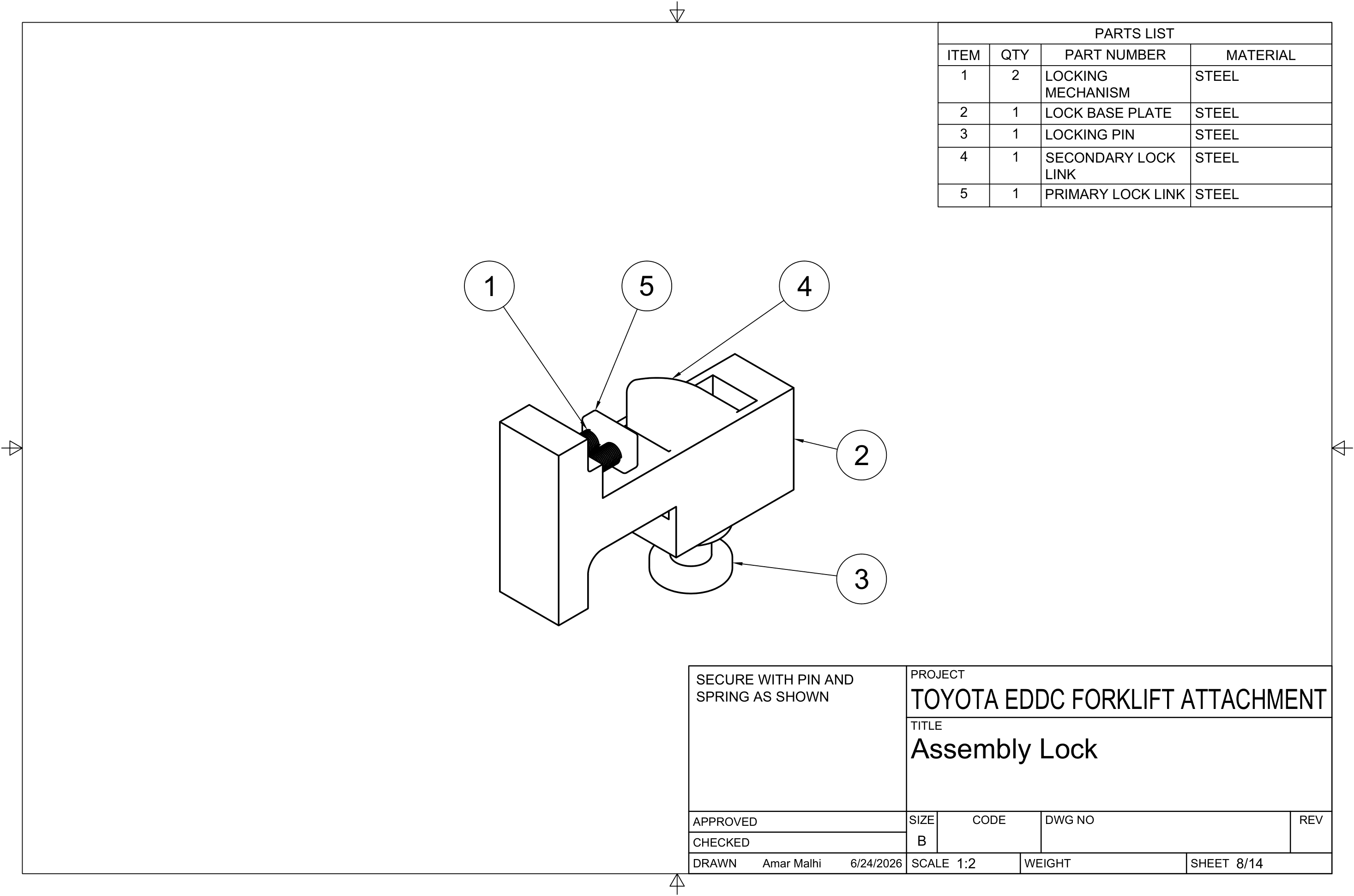
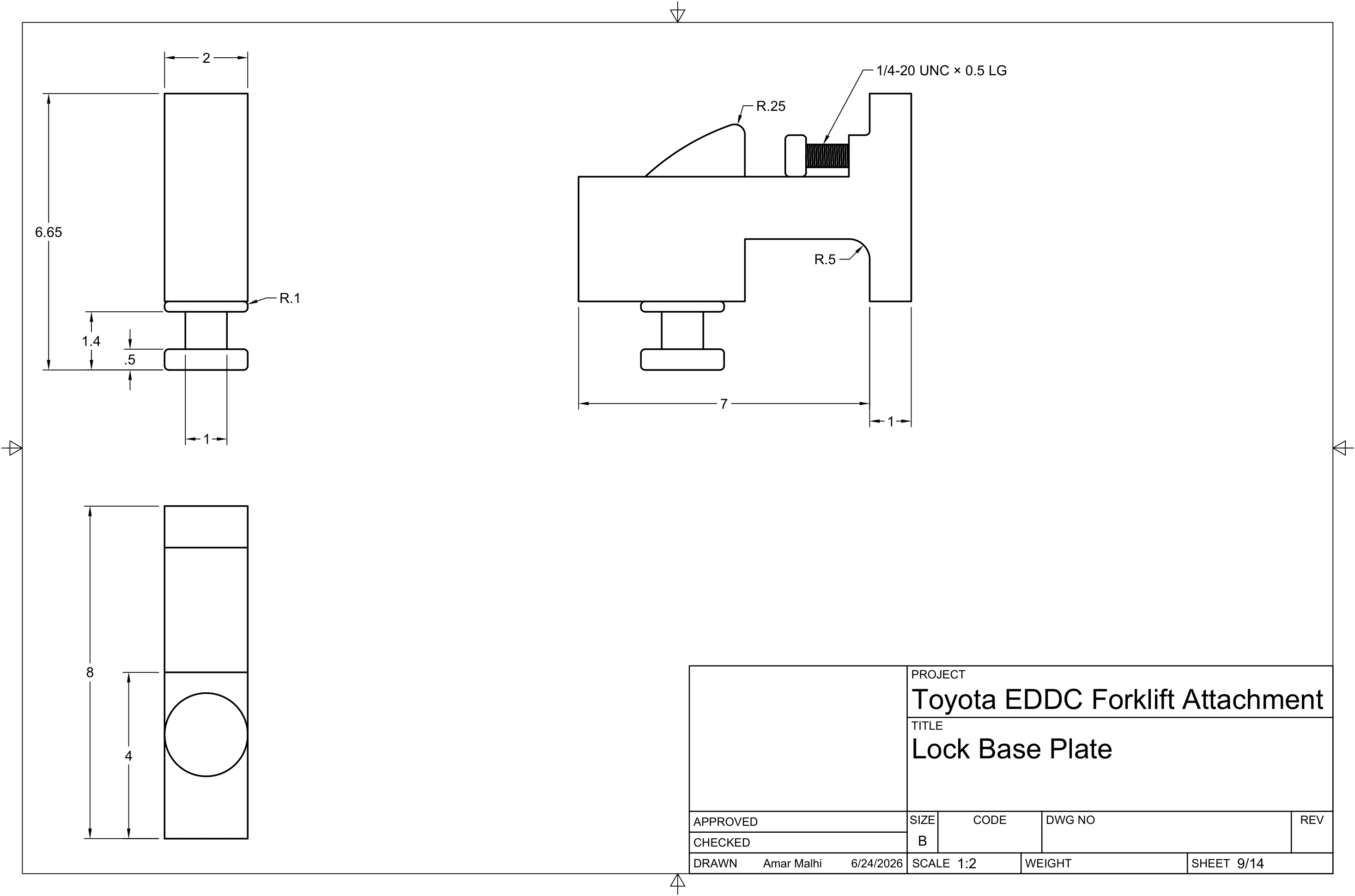
| Component 3 — Attachment Plate | Tool mounting surface | Hook-lock + spring-actuated sliding lock |
Attachments interlock via top hooks first, then a spring-actuated sliding lock engages a rectangular slot at the bottom — no hydraulics required.
| Material | Yield (psi) | Max Von Mises (psi) | Safety Factor | Trade Result |
|---|---|---|---|---|
| Titanium Ti-8Al-1Mo-1V | 131,984 | 25,837 | 5.10 | Recommended — best strength-to-weight |
| AISI 4340 Steel (normalized) | 102,976 | 25,837 | 3.99 | Strong; heavier / more corrosive |
| Alloy Steel | 89,984 | 25,640 | 3.51 | Lowest FoS in trade set |
Load case: 12,500 lb per hook (50% of Class V max per hook). Linear static FEA only — same peak stress across materials, so FoS follows yield strength; no mesh-convergence, contact, fatigue, buckling, fastener, or cost study is claimed. Drawing BOM still lists steel for the modeled CAD baseline — titanium was the recommended trade result, not a fabrication release.
| Iteration | Change | Result |
|---|---|---|
| V1 — Hook geometry | Sharp hook-to-plate intersection | Low safety factor; stress concentration |
| V2 — Fillets | Radius at hook-plate intersections | Reduced peak Von Mises stress |
| V3 — Web structures | Added support webs on hooks | Further load distribution off hooks |
| V4 — Material trade study | Steel vs. titanium vs. alloy steel | Ti-8Al-1Mo-1V recommended at FoS 5.10 |
| Rejected — Hydraulics | Extra connections & maintenance | Weight penalty; descoped |
| Rejected — Pneumatics | Air-powered actuators | Requires compressed air source |
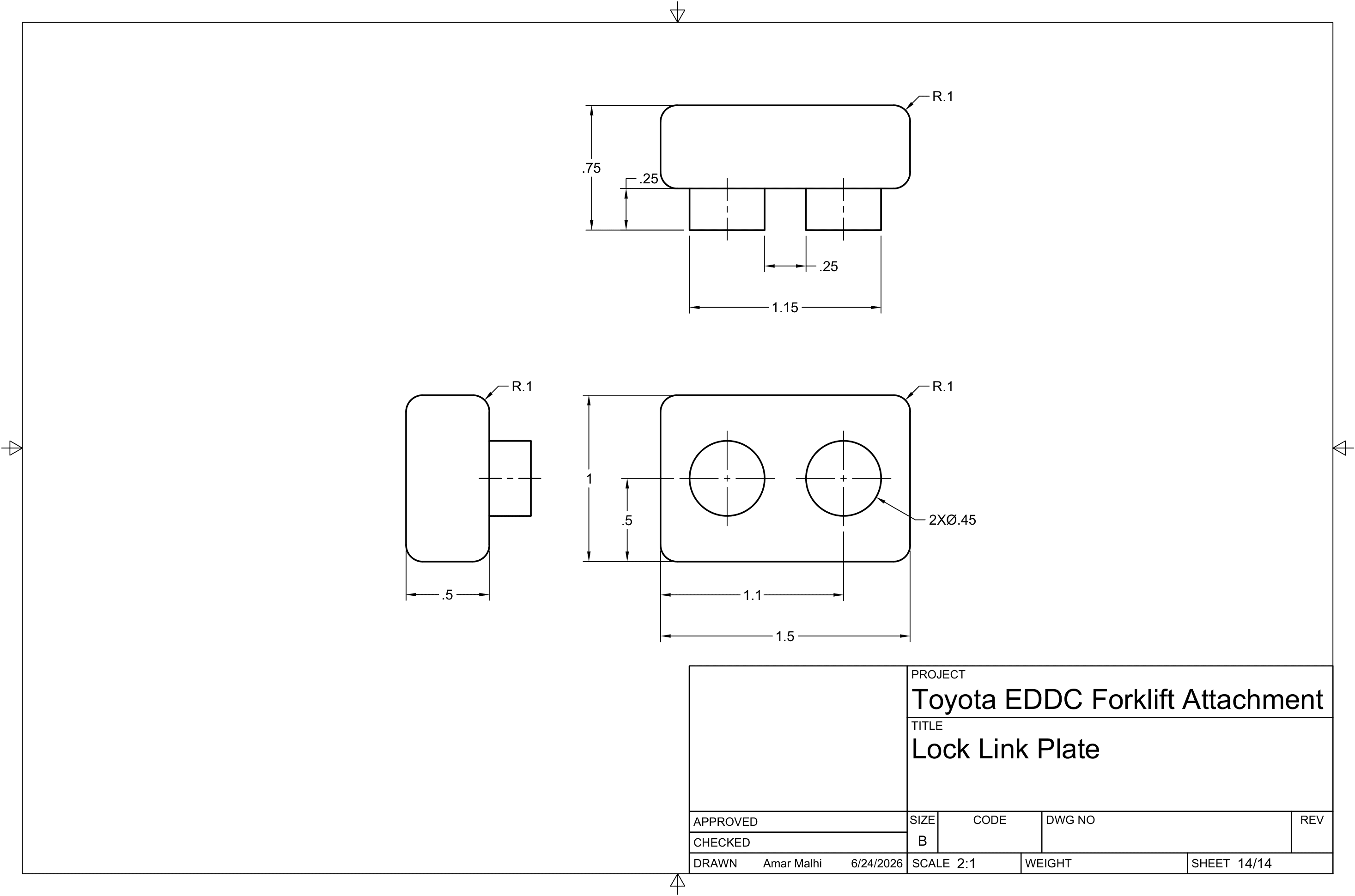
Drawing Package · 14 sheets